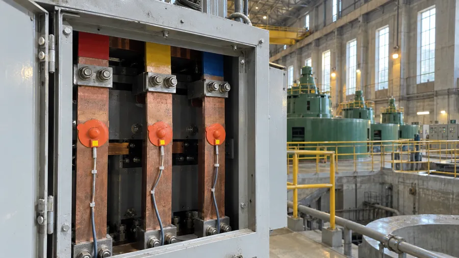
Thermalpas field deployment (Taiwan) · Thermal Risk
Taipower Mingtan Hydroelectric: generator busbars
10 yrs
in service since 2015 on 16.5 kV / 10,000 A busbars
Factory Safety · OctosX Platform
OctosX monitors heat in electrical panels, the air inside and out and the health of pumps and motors, then puts readings and alerts on LED boards where people work.
The photo shows one plant at night: an electrical room with a panel door open, a motor and pump set, a roller door to the yard with a weather mast, and an LED board above an entrance. Four views can be chosen. Heat: MCC-2, L2 busbar joint, 61.2 °C, warning. Air: machining hall PM2.5 14 µg/m³, hall A CO₂ 820 ppm and Yard B heat index Level 1, all within band. Equipment: pump P-104 drive-end vibration 6.8 mm/s, critical; CW-L1 discharge pressure 3.5 bar, below the low limit of its band. Board: the LED board above the hall entrance shows HALL A, CO₂ 820 ppm. Example values; limits are set per site.
The problem
Rounds say OK at 8 and at 3. In between, a joint warms, the hall air goes stale, a pump starts to shake, and the floor hears last.
North Plant, one day: 06:00 to 06:00
Round sheet
06:00. The round sheet says OK twice. Four things changed in between.
Factory Safety
Each area has its own sensors and its own page. They share one platform, one alert path and one record.
01 Thermal Risk Electrical room
Thermalpas contact sensors on the busbar joints inside closed switchgear.
02 Air & Environment Production hall · Yard B
Air nodes on the hall columns; a weather mast in the yard.
03 Equipment Health Pump room
Vibration and pressure on the pump set; a leak cable on the floor around it.
04 Visual Alerts Pump room door · Yard B
LED boards at the pump room door, above the hall entrance and in the yard show readings and alerts from the other three areas.
Example values; limits are set per site.
A cutaway model of one example site, North Plant. On the right, an electrical room with a row of switchgear panels; the door of panel MCC-2 stands open to show its busbar joints. In the middle, a production hall with machines, a conveyor and air nodes on its columns, and a long LED board above the hall entrance. Beside the electrical room, a pump room with a pump set, its pipes and a leak cable on the floor, and a smaller LED board at its door on the hall side. On the left, an outdoor yard with a weather mast and a third LED board. The tour moves from area to area and shows that area's example readings, which are also listed with the area tabs. Example values; limits are set per site.
01Thermal Risk
Busbar joints, breakers and lugs inside closed switchgear, read by Thermalpas contact sensors.
A switchgear room nobody opens between rounds.
Explore Thermal Risk02Air & Environment
Indoor CO₂, PM2.5, PM10, HCHO, TVOC, temperature and humidity; outdoor heat index level, noise, wind and rain. Gas (O₂, CH₄, CO, H₂S): Not explosion-proof.
A packing hall on a hot afternoon.
Explore Air & Environment03Equipment Health
Pressure, flow, leak zones, supply current and power, vibration and motor temperature on pumps and motors.
A sump pump nobody hears.
Explore Equipment Health04Visual Alerts
Indoor and outdoor LED boards show readings and alerts from the other three areas. How each board connects is confirmed per project.
A loud line entrance where phones stay in lockers.
Explore Visual AlertsHow it works
One loop for all four areas. The fourth step happens on the floor.
Sensors on the joint, in the air and on the pump, each one named for the point it reads.
The platform learns each point's normal range. Levels and rate-of-change rules are set with your team.
Each alert names the point, the reading and the change, and goes to the dashboard, email and SMS.
The same alert can be shown on an LED board at the hall entrance or a room door, where people are working. Integration is scoped per project.
Every reading and alert is time-stamped and exportable, and every acknowledgement is logged.
The Sense step: each sensor reads one point, such as a busbar joint inside a closed panel, the air in the machining hall, the drive end of pump P-104 and the floor around its skid.
The Watch step: pump P-104 has run inside its learned range all night. At 02:28 its drive-end vibration starts climbing faster than its rate-of-change rule allows, from a 2.8 mm/s baseline, and passes its critical level at 02:54. Example values; limits are set per site.
The Alert step: at 02:47 the leak line reports zone B wet, under the CW-L1 discharge flange in the pump room. The alert names the point, the reading and the change, then goes to the dashboard, email and SMS.
The Show step: the same alert can be shown on the LED board at the pump-room door, ALERT, LEAK · ZONE B, in the critical colour. Which readings, which alerts, and how each display connects are confirmed for each project.
The Record step: the rate-of-change flag at 02:28, the leak at 02:47, the board's alert page at 02:47 and the on-call acknowledgement at 02:51, each time-stamped and exportable.
The OctosX Platform
Plant status first, what changed overnight next, and the reading behind every alert.
Screens are configured per site during commissioning.
Where the record comes from
10+ years of Thermalpas service in Taiwanese power plants, fabs and transit systems.
Thermalpas field deployment (Taiwan) · Thermal Risk
10 yrs
in service since 2015 on 16.5 kV / 10,000 A busbars
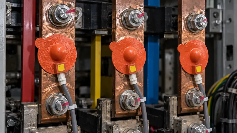
Thermalpas field deployment (Taiwan) · Thermal Risk
3
anomalies caught before the red threshold over five years
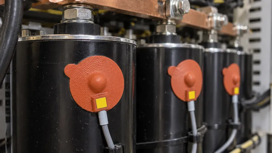
Thermalpas field deployment (Taiwan) · Thermal Risk
Independent reviewSensor technology reviewed by Prof. Masafumi Kimata, Ritsumeikan University
All field casesField cases on this site are Thermal Risk deployments of the Thermalpas sensor.
We describe these areas by what they measure and how they are used, not by results.
Where the lines are
Tell us about your site. We'll reply with a scoped proposal for one area or all four.